

Modeling and Texturing Cut and Fill in 3D for Roadway Projects
As we have discussed before, terrain is one of the most difficult parts of 3D modeling and visualization in civil engineering. One of the most common uses of terrain modeling in civil visualization is the cut and fill of roadway jobs which is the subject of today’s conversation.
Depending on the stage of the project, you as the visualizer may be tasked with the roadway modeling or it might have already been done. If it is in the concept/alternative phase, exact engineering probably isn’t going to be required but it does need to pass the smell test and look right. While I’ll save the roadway design jargon for another day, make sure you are working with an experienced roadway designer in this process so that it at least looks right, even if it is in the early planning stages. InfraWorks has probably the quickest roadway modeling tools and they are getting better, but remember that InfraWorks is primarily a planning product and that the results of your modeling shouldn’t be referenced for actual construction documents.
If the project has all or mostly been designed, you may be fortunate enough to work with design surfaces. If you know the ins and outs of Civil 3D or In Roads, you can make the surfaces yourself based on alignments and roadway sections. If you have this capability, modeling the cuts and fills using actual design software like Civil 3D or In Roads is desirable. These tools are robust and accurate and the surfaces created can act as a great foundation for your model.
Modeling can be the most difficult, but it actually isn’t the part that matters the most from a visualization perspective. The difference between a 2:1 and a 3:1 slope is probably difficult to see from an animation, but if you get the texture wrong, it will instantly be noticeable.
The trick of texturing cut and fill sections is that it is usually disturbed soil and should be treated as such. The knee jerk reaction would be to simply find a texture in the modeling software you are using that looks kind of right, but this isn’t the best option. The best option for texturing cut and fill areas is to use photo editing software such as photoshop to custom texture these areas and then drape the image on top of the surface. This can be difficult not only to preform but to get it to look right so make sure you test this out on some practice projects first before doing work for your firm or client.
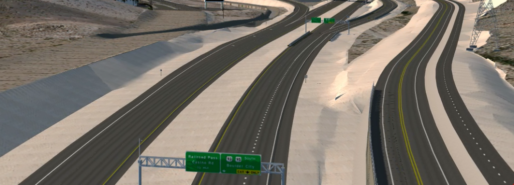
The next best alternative to the custom texturing in photoshop method is to find a similar area and make a custom, repeating texture. To do this you simply find an area near this project that has been constructed in the past 5 or 10 years (the more recent the better), clip part of the disturbed soil image in Google Maps or Earth and then use this as the base of a texture that you will use for your model. I used this method for this project and the results were fairly good. This project was modeled in InfraWorks but I used surfaces from InRoads to ensure accuracy.

There are also just a few more items of consideration in the cut and fill texturing process. The first is that cuts usually look different from fills. Fills are almost always engineers (compacted) soil while cuts will be representative of whatever the in-situ conditions of the soil are at that location. For soft areas the cuts and fills may look similar but for deep mountain cuts the cut area could be very rocky and look like something from a geology text book. These are the areas that most benefit from the custom photoshop method.
Also keep vegetation into consideration. If you live in Nevada like I do, cut and fill areas are usually void of vegetation for many years after construction, saving hydro seeded areas. If your project has a lot of vegetation, remember that you may need to make the texture look like soil or grass and then add the trees and bushes as 3D models later.
And finally, try and ask your client what they want for their project. Ask if they want it to look like ‘new construction’ if if they want it to be more representative of what it will look like a few years down the road when the project looks more natural and organic. Asking these questions and performing to their desired outcome will really set you apart from the competition (whether it be internal or external) for 3D visualization.
Roadway and other transportation 3D visualization projects are often the most difficult to get right but they can also be the best for your portfolio or for your bottom line as they are often the largest.
Great post Sam. I agree with you and great insight. On many 3d projects related to roads or highways, you have a lot of cull and fills, slopes on either sides of the road. These need to actually reflect what they are. Texturing come in as a very important part of making a 3d image reflect what is being designed. I think another part is what software you can used to develop the slope or cut and fills, and how to texture them. I would in 3dsmax unwrap the UWV mapping and paint over in PhotoShop.
Thanks for sharing